Choose an aluminum enclosure for two PCBs by deciding how the boards will sit inside it before selecting the body size. A side-by-side layout needs enough internal mounting area. A stacked layout needs enough height for both populated boards and the space between them. Both arrangements also need a practical way to install, connect and remove the boards.
The smallest enclosure that contains two bare circuit boards may not suit the finished device. Components, supports, connectors and the opening method can change the required size. This guide explains how to compare aluminum enclosure products using the complete electronic assembly, with a simple height example for a stacked arrangement.
Collect the outline, thickness and component heights for each board. Include parts on both sides, projecting connectors and any attached modules. Use drawings or models of the populated boards rather than only their bare outlines.
Next, show how the boards connect. A short internal cable and a rigid board-to-board connector can create different layout requirements. Record where the connections are made and whether they must be reached during assembly or service.
Do not assume that two boards fit because their combined area is smaller than the enclosure floor. Their shapes and positions matter. A usable mounting region may also be interrupted by internal ribs, corners, guides or attachment features.
At this stage, prepare two rough arrangements if both are possible. Comparing them before the enclosure is fixed can reveal a simpler product choice.
Putting boards beside each other can make both boards visible after the cover is removed. Stacking them can reduce the floor area occupied by the boards, but it adds a height check and can make the lower board harder to reach.
These are starting points for a mechanical review, not promises about cooling, electrical performance or ease of assembly.
| Selection question | Side-by-side boards | Stacked boards |
|---|---|---|
| What space is most important? | Available internal length and width | Available internal height and support positions |
| Can both boards be reached? | Check access around each board | Check whether the upper board blocks the lower board |
| How are the boards supported? | Confirm supports or a mounting plate for both | Confirm a suitable support arrangement at both levels |
| How do the boards connect? | Check the route between the boards | Check connection height and assembly order |
| How do external interfaces align? | Review both boards against the panels | Review interface positions at each board level |
| What must be checked before ordering? | Complete layout and mounting-area drawing | Complete height stack and mounting arrangement |
Table 1. Qualitative comparison. Actual suitability depends on the selected enclosure and complete electronic assembly.
 Figure 1. Board arrangement changes the space needed inside the enclosure. These diagrams do not establish electrical spacing, airflow or a supplied mounting configuration.
An enclosure with removable end panels may suit an assembly designed to slide through an end. A removable-cover enclosure may offer a more direct route to boards placed inside from above. Confirm the actual construction of the chosen model.
For an end-entry design, check whether the two boards enter together or separately. Include every populated component and support in the insertion check. A board that fits in its final position may still catch on another feature while being installed.
For a removable-cover design, check the clear opening. The space near the bottom of the enclosure can differ from the opening through which the assembled boards must pass.
Browse Evernice’s aluminum enclosure range to identify starting products, then request the relevant internal and assembly drawings. Do not select the opening method from the exterior appearance alone.
Place both populated boards within the actual usable mounting region. Leave space for their supports, internal connections and the assembly work required between them.
A wider enclosure may solve a width problem, while a longer enclosure may allow a different board arrangement. Compare both options rather than increasing every dimension at once.
Also review the panel layout. If each board carries an external connector, both connector positions must work with the enclosure walls or end panels. Keeping the boards close together internally is not useful if the external connections become inaccessible.
If the boards use a common mounting plate, include the plate and its position in the drawing. A plate can provide a separate surface for arranging the electronics, but its availability and attachment method must be confirmed for the selected enclosure.
For stacked boards, measure from a common reference at the enclosure floor. Include the lower board position, both board thicknesses, component heights and the intended gaps.
The example below assumes that the tallest relevant features face one another in the same area. If they occupy different areas, a detailed three-dimensional layout may give a different result.
| Height item, from bottom to top | Assumed value |
|---|---|
| Floor to underside of lower PCB | 4.0 mm |
| Lower PCB thickness | 1.6 mm |
| Components above lower PCB | 12.0 mm |
| Gap between facing components | 3.0 mm |
| Components below upper PCB | 2.0 mm |
| Upper PCB thickness | 1.6 mm |
| Components above upper PCB | 10.0 mm |
| Gap below the closed cover | 3.0 mm |
| Total internal height needed in this example | 37.2 mm |
Table 2. All values are hypothetical. They are not Evernice specifications, recommended gaps or electrical safety distances. The 4.0 mm lower space is assumed to accommodate the lower board’s underside features and required mechanical separation.
The arithmetic is:
4.0 + 1.6 + 12.0 + 3.0 + 2.0 + 1.6 + 10.0 + 3.0 = 37.2 mm.
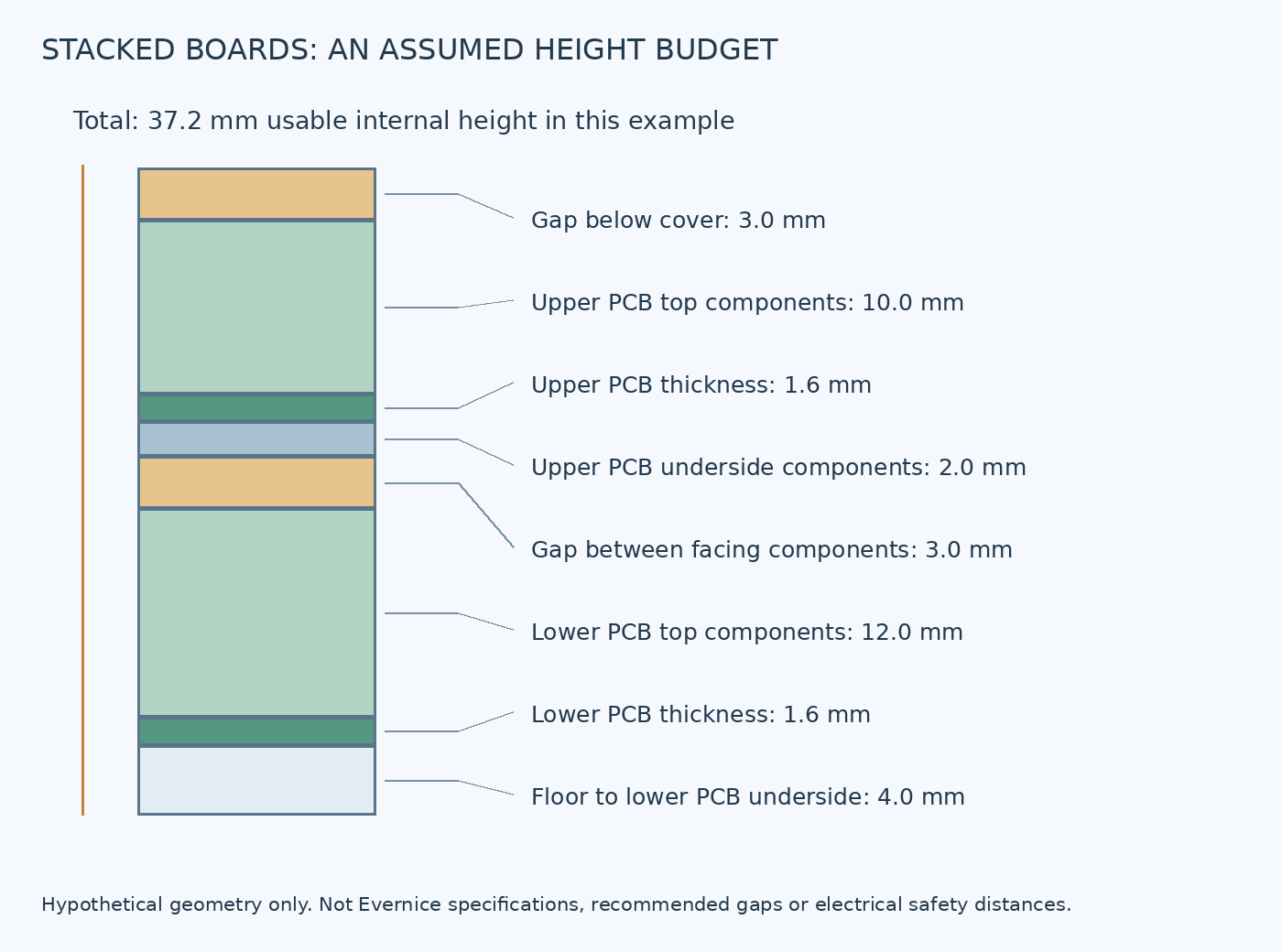
Figure 2. A hypothetical height budget for two boards. It is a dimensional illustration, not a recommended mounting design or verified fit.
Compare the result with the usable closed-cover height at the relevant locations. Do not compare it directly with an external catalog height.
This calculation is only a starting check. Review dimensional variation, support geometry and the actual components before approving a design. If a rigid connector establishes the board spacing, use its assembled dimensions to check the relationship between the boards.
Enough space does not automatically mean there is a suitable way to hold the boards.
Check the mounting points or guide positions in the selected product drawing. If an extrusion has several internal grooves, confirm which are intended to support the proposed boards. The grooves may not provide the required board positions or fit every board thickness.
For two boards of different widths, do not assume that both will fit the same opposing guides. Discuss an appropriate support arrangement or another enclosure size with the manufacturer.
Keep the support method in the assembly drawing. It should show how each board is located and retained, and how it can be removed. Avoid leaving the mounting design to be resolved after the enclosure has been machined.
Show the complete installed position of each external interface. A connector on the upper board and another on the lower board may need openings at different heights.
Use the component drawings to place those openings. Also include the space needed behind the panel and the external mating parts. A cutout can fit the visible connector while another part of its assembly conflicts with a board or enclosure feature.
If the interfaces cannot be aligned without compromising the board arrangement, compare another profile, panel size or internal layout before approving machining. Changing the panel alone may not solve an unsuitable board position.
Ask what happens when the lower board needs inspection. Does the upper board have to be removed? Can internal connections be released without pulling on the boards? Check the intended sequence with the actual layout.
Do not assume that a stacked arrangement will cool adequately because the body is aluminum. Nor should a side-by-side arrangement be treated as a thermal solution by itself. Evaluate the equipment under its intended operating conditions.
Mechanical gaps also do not establish electrical clearance or insulation suitability. The responsible designer must assess those requirements separately. Keep the hypothetical gaps in this article out of electrical safety specifications.
Before approving production, review a sample with both intended boards, supports, connections and panels installed.
Check board insertion, panel closure, external connection access and removal for service. Confirm that the assembly seats naturally rather than needing the boards or enclosure to be forced into position.
Record the enclosure and PCB revisions used. A later component-height change or connector substitution can affect a layout that previously fitted.
When requesting a quotation, provide the populated-board dimensions, preferred arrangement, panel openings and intended installation. Ask the supplier to identify the body and support configuration clearly so both parties review the same product.
Evernice offers aluminum enclosure options and CNC machining services for electronic products.
Send the dimensions of both populated boards, their proposed positions and the required panel layout through the Evernice inquiry page. We can discuss suitable starting models and the drawings needed to review the configuration.


