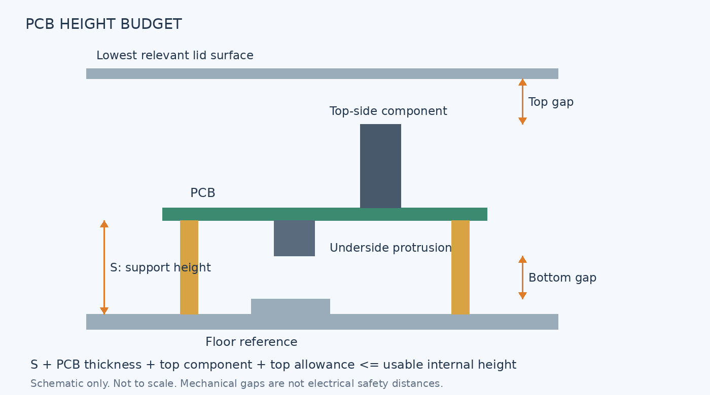
Use maximum dimensions from the relevant drawings where available. If a dimension is provisional, mark it as an assumption to resolve before release.
2. Calculate the Minimum Support Height
The underside of the PCB must sit above the highest obstruction beneath it, with an appropriate mechanical allowance.
For a conservative first check, use:
Minimum support height = floor obstruction height + underside protrusion + bottom allowance
The floor obstruction height is measured from the chosen floor reference. The underside protrusion is measured down from the PCB underside. The bottom allowance is the mechanical gap your design requires after considering dimensional variation and assembly needs.
This expression assumes that the obstruction and protrusion could overlap in plan view. A detailed three-dimensional check may show that they occupy different locations, allowing a more compact arrangement.
Do not count the support itself as an obstruction where it intentionally contacts the board. Instead, define a component and copper keepout appropriate to the mounting hardware and electrical design.
Also distinguish molded-boss height from added-spacer height. If the board sits on a spacer mounted on a boss, both contribute to the total support stack.
3. Calculate the Maximum Support Height
Raising the board reduces the space above it.
Using the same floor reference, calculate:
Maximum support height = usable internal height − PCB thickness − top-side component height − top allowance
Top allowance is the mechanical space reserved between the tallest relevant feature and the lid. Select it from the assembly requirements and dimensional stack, rather than borrowing a general value from an unrelated design.
Include a screw head or mounting feature above the board if it is taller than nearby components. If a cable or mating connector rises above the PCB assembly, check that envelope too.
A feasible arrangement needs:
Minimum support height ≤ selected support height ≤ maximum support height
If the range is empty, changing the spacer alone will not solve the layout. Review a deeper enclosure, a different component position, a different board orientation, or an alternative mounting arrangement.
4. Worked Example: Can an 8 mm Support Height Fit?
The following numbers illustrate the calculation. They are not Evernice product dimensions or general clearance recommendations.
| Parameter | Example value |
|---|---|
| Usable internal height from floor reference | 28.0 mm |
| Obstruction beneath the relevant board area | 1.5 mm |
| Maximum underside protrusion | 3.0 mm |
| Bottom mechanical allowance | 1.0 mm |
| PCB thickness | 1.6 mm |
| Tallest top-side component | 15.0 mm |
| Top mechanical allowance | 1.5 mm |
The minimum support height is:
1.5 + 3.0 + 1.0 = 5.5 mm
The maximum support height is:
28.0 − 1.6 − 15.0 − 1.5 = 9.9 mm
An assembled support height of 8.0 mm lies within this preliminary range.
The estimated bottom gap is:
8.0 − 1.5 − 3.0 = 3.5 mm
The estimated top gap is:
28.0 − 8.0 − 1.6 − 15.0 = 3.4 mm
These nominal results do not replace a worst-case tolerance review. Check actual support-height variation, board thickness, component heights, and enclosure geometry before approving the design.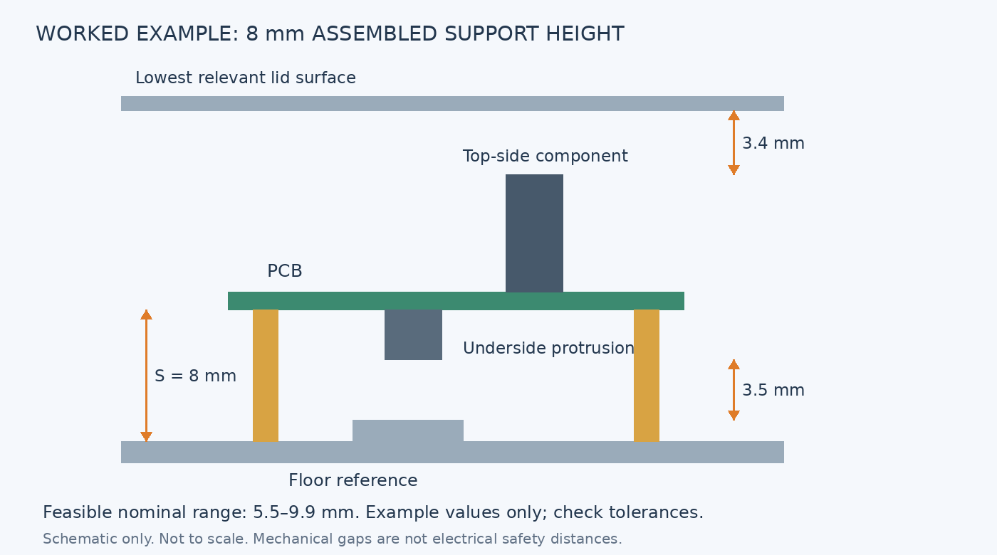
Figure 2. An 8 mm assembled support height fits the example’s nominal vertical budget. Connector alignment and dimensional variation still need review.
5. Check Connector Alignment Before Choosing a Standard Spacer
A support height can satisfy the lid and floor checks while placing a connector incorrectly.
Measure the connector’s mounting or mating reference relative to the PCB. Then locate that reference in the enclosure using the selected support height. Compare it with the panel cutout and the connector manufacturer’s installation drawing.
For a connector whose centerline is defined above the PCB top surface:
Connector centerline above floor = support height + PCB thickness + centerline offset above PCB
Use that relationship only when the offset is actually specified from the PCB top surface. Other drawings may reference the board underside, mounting face, or another datum.
Review the mating plug and cable, not only the board-mounted connector. Include access to release tabs, screws, and cable bends.
If the panel opening is already fixed, connector alignment may determine board elevation first. The remaining task is checking whether the lid and floor provide enough space at that elevation.
6. Review Fasteners, Support Locations and Electrical Requirements
Choose mounting hardware using the actual board and enclosure interfaces.
For threaded supports, confirm thread designation, screw length, engagement, and whether the screw can bottom out. For snap-in hardware, confirm PCB thickness and hole dimensions against the specific part drawing.
Review support contact areas around mounting holes. Keep components clear of the hardware envelope and decide whether a conductive support is permitted to contact the board at that location.
Mechanical clearance is not the same as electrical clearance or creepage. Do not use the example’s 1 mm or 1.5 mm allowances as electrical safety distances. Electrical spacing must be determined from the applicable equipment requirements and circuit conditions.
Likewise, a plastic support does not by itself establish a compliant insulation system. Review material and assembly requirements within the complete product design.
7. Verify the Assembly Sequence and Prototype
Check how the board reaches its final position.
A board that fits after installation may still be difficult to lower past screw towers or insert beneath an overhanging feature. Review the insertion path, tool access, and the order in which connectors and wiring are installed.
Build a prototype with the intended PCB, supports, fasteners, and mating connectors. Confirm that the board seats without being forced and that tightening does not visibly distort it.
Fit the lid and check the planned clearances. Include any wiring added during final assembly. Record the enclosure and PCB revisions used for the check.
If a later component substitution increases height, or a new support changes board elevation, repeat the affected mechanical review before production.
PCB Standoff Selection Checklist
| Check | Information to confirm |
|---|---|
| Reference geometry | Common floor datum and local usable lid height |
| Board envelope | Thickness, upper components and underside protrusions |
| Support stack | Boss, spacer, washer and installed board elevation |
| Connector position | Reference height, cutout alignment and mating access |
| Hardware | Hole size, screw length, thread and support contact area |
| Design validation | Dimensional variation, electrical requirements and prototype fit |
Evernice manufactures electronic enclosures and provides customization services for enclosure projects. Browse our plastic enclosure range to identify potential starting models.
For panel openings and other modifications, review our customization and CNC machining services. When discussing a project, provide the board outline, mounting-hole positions, component-height envelope, connector drawings, and intended support stack.
You can contact Evernice to discuss enclosure options and the information needed for a quotation.


